
Handling Exercises
Problem definition:
Handling tasks are very common in production. Not only industrial robots are used for this, but also so-called2-axis handling systems for simple movements. One then often speaks of Pick & Place tasks when a workpiece is only placed from one location to another. Examples are:
Handling tasks are very common in production. Not only industrial robots are used for this, but also so-called2-axis handling systems for simple movements. One then often speaks of Pick & Place tasks when a workpiece is only placed from one location to another. Examples are:
- Taking down a workpiece from a conveyor belt
- Inserting one workpiece into another (assembly)
- Placing a workpiece in a package
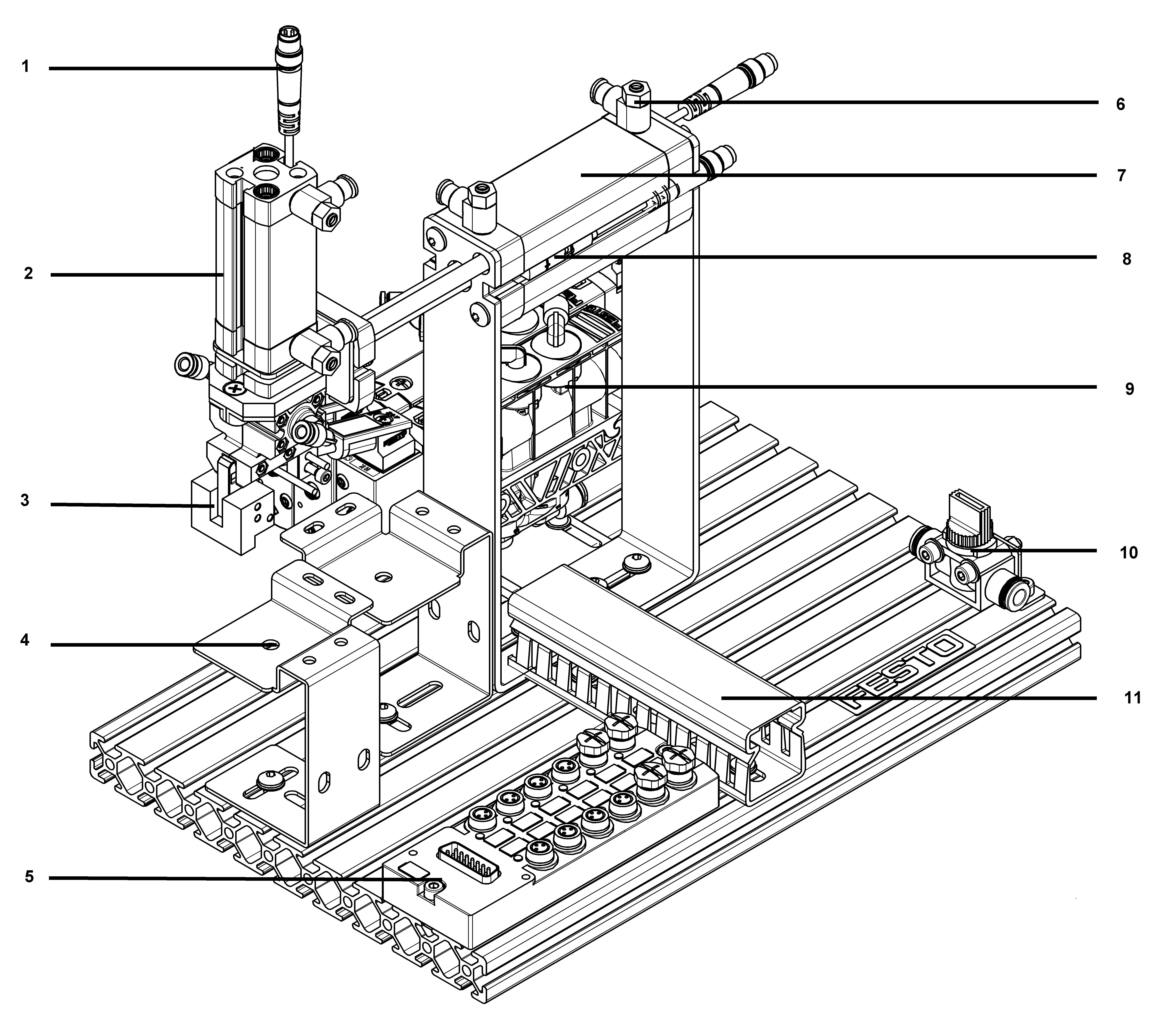
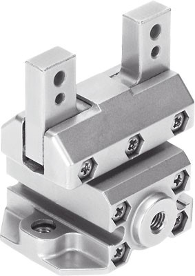
Match the components with their correct designation and describe their purpose within the station.
Function Description
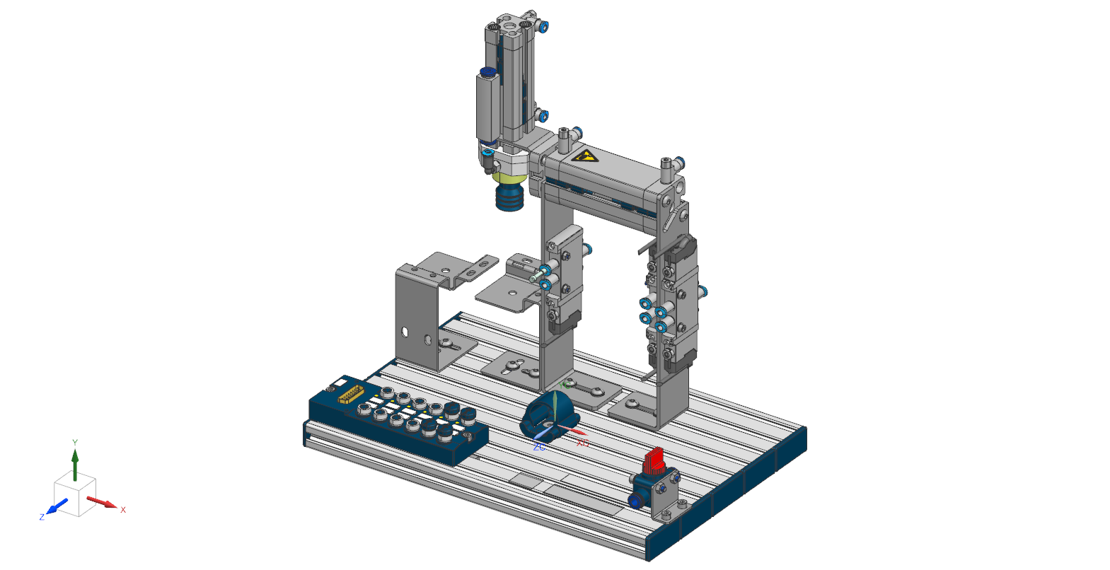
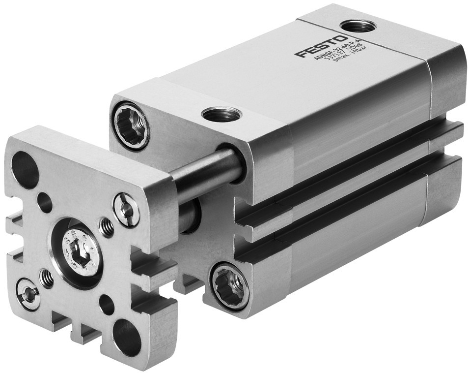
In this second exercise will discuss the function of the Handling Station. Using two pneumatic cylinders, a workpiece is picked up and placed. This supposedly easy task requires many functional components, which will be described now.
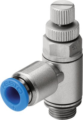
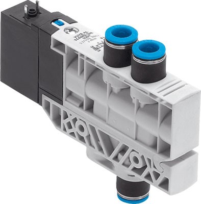
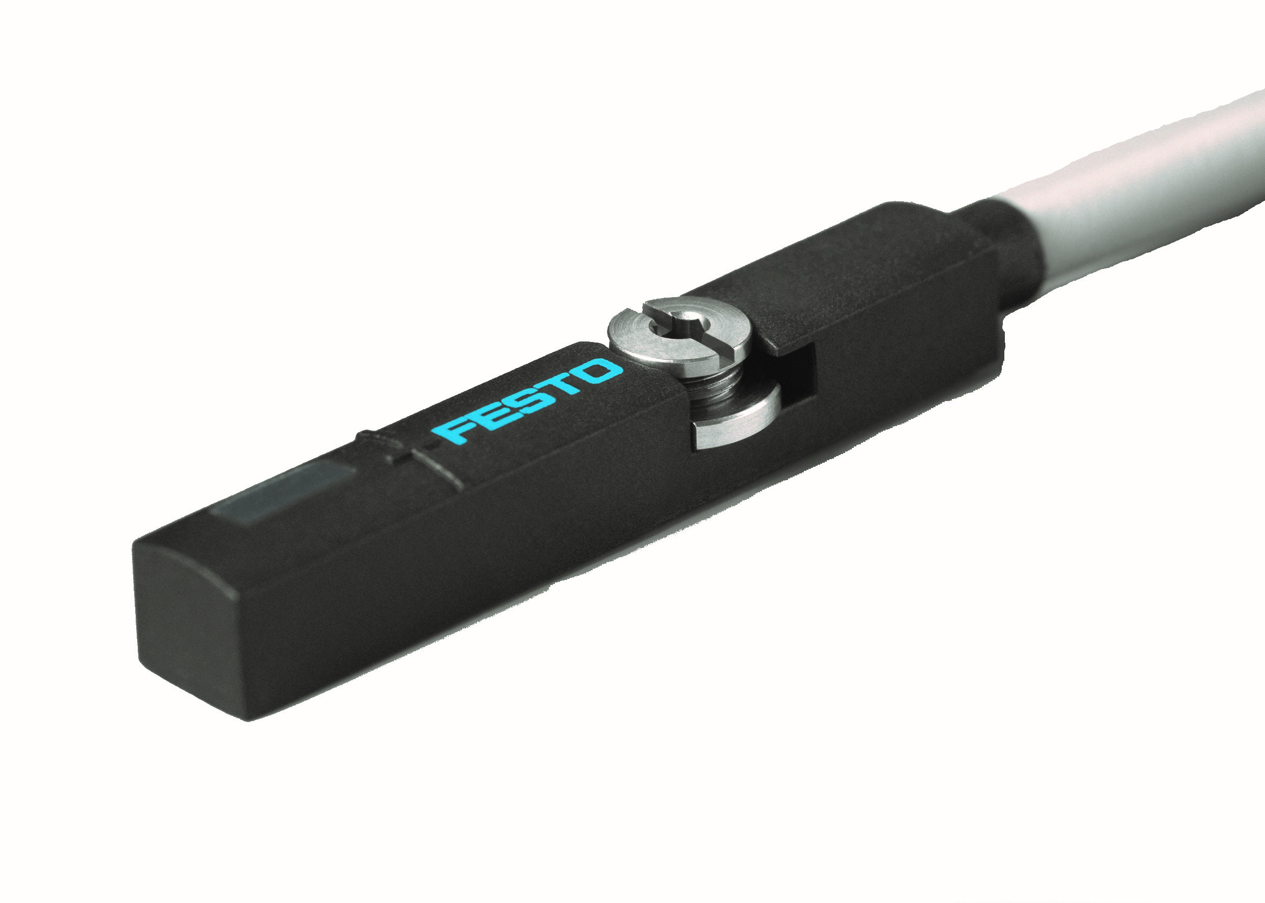
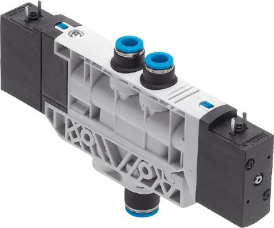
All components are mounted on a baseplate. The workpiece is gripped by a gripper, which is attached to a double-acting cylinder. The gripper moves in z-Direction and places the workpiece on the storage plate. The second double-acting cylinder moves each workpiece in x-Direction. For each cylinder two magnetic proximity sensors are used to detect the piston's position. Compressed air flows into the cylinder passing a one-wayflow control valve and pushes the piston in its final position. This type of valve can be used to regulate the piston's speed in both directions. In order to pick up and place the workpiece in the right order, the cylinders have to be moved in a specific sequence. This is possible by controlling solenoid valves, which open and close air ducts. Compressed air can be turned off by manually closing a 3/2-wayhand valve.
Within this station all actuators and sensors need an electrical connection in orderto work, send and receive signals. The multi-pin plug distributor offers enough plugs for each sensor and actuator. A cable duct collects all cables for a neat installation.
No.
Designation
Function within the station
1
2
3
4
5
6
7
8
9
10
11
Learning about components, symbols and designations
Learning objective
Upon completing this exercise, you should be familiar with the symbols and designations of key pneumatic components
Problem description
All automated systems use a range of components such as sensors, valves, motors, etc. It is important to describe the function of the system clearly and simply. This is done using, among other things, electrical, pneumatic and hydraulic circuit diagrams. To understand these circuit diagrams, you must be familiar with the symbols used.
Match the components and symbols with the correct designations. Do this by dragging the designation to the component in the correct fields in the “Designation” column.
Component
Symbol
Designation


MBSE - Exercise Description
The Handling Station can be designed as a (sub-)system of a bigger production line. Systems modelling has increased in importance because of the complexity of modern systems. Model Based Systems Engineering (MBSE) is the computed aided method of conceptualizing and designing such systems. A commonly used description language is the Systems Modelling Language (SysML) which has some similarities to the Unified Modeling Language (UML).
With the first exercise, we learned how to describe the structure of a system. In this exercise, we will focus on the behavior of the system. The behavior can be described with interactions between components. An interaction is characterized by the exchange of messages a state transfer. In the following table, you will find everything you need to complete this exercise.
With the first exercise, we learned how to describe the structure of a system. In this exercise, we will focus on the behavior of the system. The behavior can be described with interactions between components. An interaction is characterized by the exchange of messages a state transfer. In the following table, you will find everything you need to complete this exercise.
UML
SysML
Name
Symbol
Description
Example
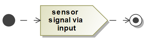
Activity Start

Starting point for an activity
Activity End

Ending point for an activity
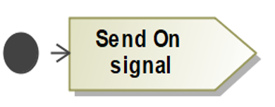
Send Signal Action
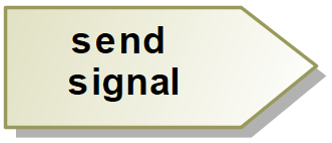
Sends a signal via a port
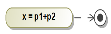
State
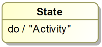
Represents the current state of a component
Exercise:
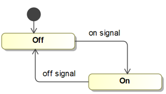
The Handling Station is used to pick up workpieces and place them on a storage plate. To do so, two pneumatic cylinders work separately in a defined order. The behavior of this process can be described with states and activities. The vertical cylinder the moves the gripper start in Standby-State. The piston will move in positive z-Direction when air enters the cylinder through the one-way valve. When the whole movement is completed the piston reaches the final position. With entering this state, the activity send sensor signal is started. The signal is sent through a port called output_cylinder. The piston stays in the state waiting until again air enters the cylinder through the second one-way valve. Now, the piston moves in negative z-Direction until it reaches the starting position. Again a magnetic sensor detects the piston an sensor signal is sent through the output_cylinder port.
Complete the State- and Activity-Diagram down below using all elements. Drag and drop the activities and states into the pictures.
Pool of elements and relationships
Inspired by Festo